Dimension table for duct insulation
In the Dimension Table Edit dialog, administrator can allow the program to generate insulation for air duct parts that have been modeled as GDL components, so that their insulation can be shown in work views and drawings, and be included in material listings.
This special configuration only applies to non-cylindrical air duct components. The insulation of cylindrical air duct components is handled in the same way as the insulation of pipes.
Enabling shape parameter formulas
In the Dimension Table Edit dialog, the Insulate air duct part as section is not visible unless specific conditions are met.
Do the following:
-
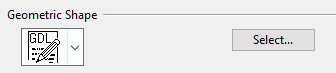
In the Geometric Shape section, select the component model.
-
Select GDL as the shape type.
-
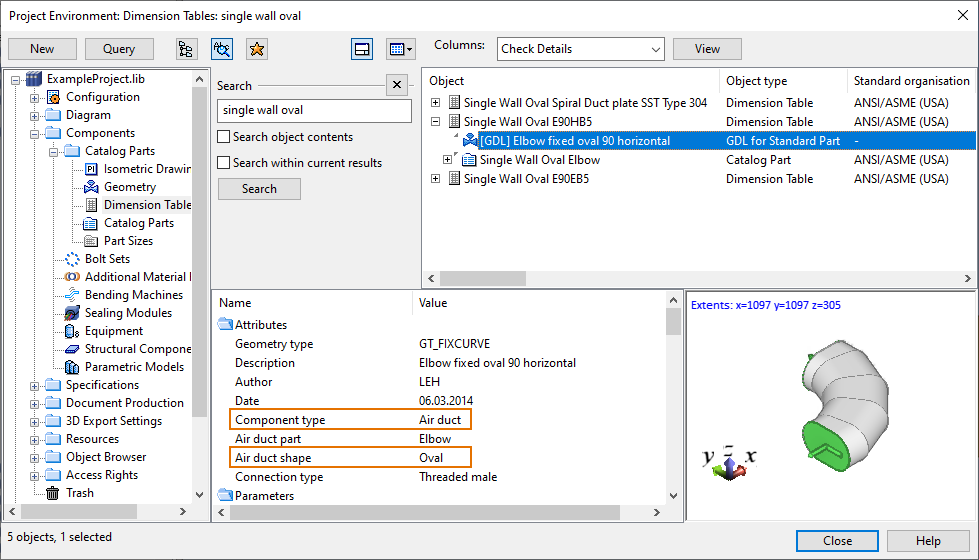
Click Select and select a GDL component that has these attributes:
-
"Component type" is "Air duct".
-
"Air duct shape" is NOT "Circular" but some other shape.
-
-
-
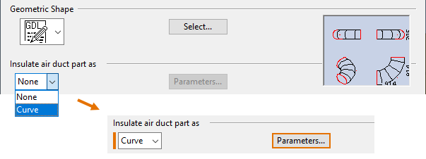
In the Insulate air duct part as section, select the geometric shape of the insulation. The Parameters button is enabled.
-
Click Parameters and define the shape parameter formulas for the insulation as described in Defining shape parameter formulas.
Defining shape parameter formulas
In the Edit Shape Parameter Formulas To Model Insulation for … dialog, you can specify a calculation formula for each dimension parameter that is used for generating insulation for the specified air duct part modeled as a component. The formulas allow the geometry of the insulation to be derived from the Dimension Table parameters of the air duct part, so that insulation can be generated for all available part sizes.

-
The Dimension line to evaluate models field lists the first ten Catalog Part sizes of the air duct part. When you select a sample part size from the list, you can see its dimensions as a list and also graphical representations of the part. These are shown just to make it easier to refer to dimension names in the formulas.
-
The Formulas for shape parameters pane lists the parameters that define how the inner cross-sectional dimensions of the insulation are calculated from the outer dimensions of the air duct. You can modify the geometry of the insulation by editing the calculation formulas.
Double-click a parameter to open its formula for editing. In the formula editor, you can use numbers, names of dimension attributes, arithmetic operators + - *, and parentheses ().

The changes in duct insulation settings are applied to work views when you close the Project Environment dialog. In the example below, the two selected duct parts have been modeled as components, and their insulation has been defined with the settings described above. As can be noticed from the picture, oval-shaped air duct components display a rectangular insulation shape.
